
![[object Object]](https://omo-oss-image.thefastimg.com/portal-saas/new2023080419495759710/cms/image/138ba837-b50d-4ff3-a73c-2e6a2379c522.jpg "[object Object]")


Acrel APM510/WF CE Approved Digital 3 Phase WiFi Energy Meter For IOT Platform Energy Consumption Monitoring
Series of products: Products
Series of products: Power Monitoring and Controlling Devices
Series of products: Energy Management
Series of products: Three Phase Energy Meters
Series of products: AC Energy Meters
Series of products: Panel Installed Energy Meters
Series of products: Panel Installed AC Energy Meters
Series of products: Programmable Energy Meters for Switchgear Assembly
Series of products: Wireless Energy Meters


- Product Description
- Parameters
- Q&A
- Download
-
Overview
APM5 series network power meter (hereinafter referred to as the meter) is designed according to IEC international standards, with full power measurement, power statistics, power quality analysis (including harmonics, interharmonics, flicker), fault recording function (including voltage temporary rise and fall interrupt, inrush current and other records), event recording function and network communication and other functions.
It is mainly used for comprehensive monitoring of power supply quality in the power grid.
This series of meters is equipped with feature-rich DI/DO modules, AO modules, wireless communication modules, leakage temperature measurement modules, which can flexibly realize the full electrical circuit Power measurement and switching status monitoring.
Dispaly
Code Rule
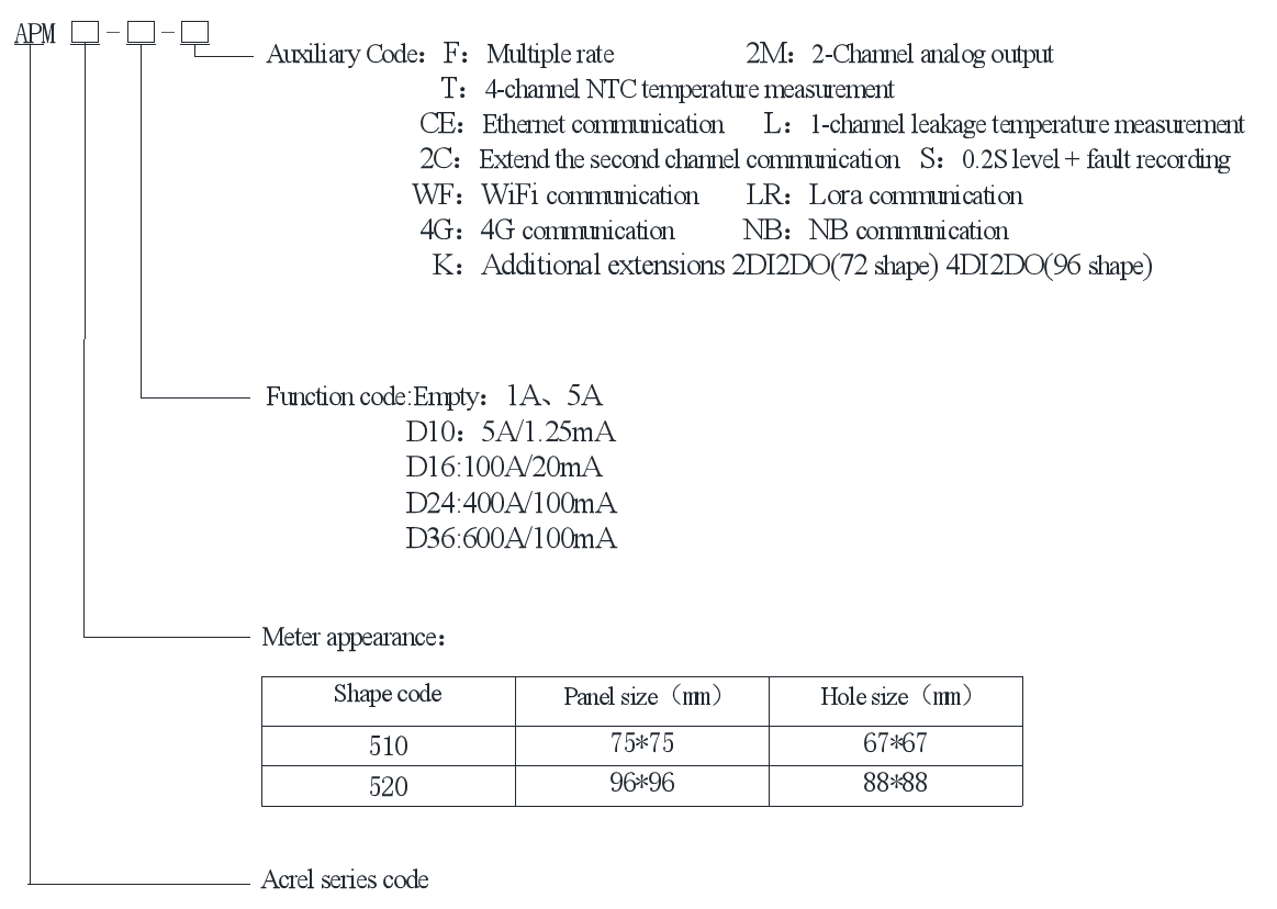
Note:1、When the meter is connected by 5A/1.25mA as the two-time mutual inductance method, the meter's own secondary-side transformer should be kept at a distance from the on-site primary-side transformer to avoid out-of-line interference.
Function
● 3 phase 3 wires, 3 phase 4 wires
● Rated voltage: AC 3*57.7/100V, AC 3*63.5/110V, AC 3*230/400V, AC 3*400/690V (96 Shape only);
● Rated current: 1A, 5A
● Accuracy: IEC 62053-22 0.5S class (0.2S accuracy when S is selected)
● Communication: RS485(Modbus-RTU)、Ethernet (MODBUS-TCP)、WiFi、4G
● 2DI+2DO
Electricity Data Measurement
● kWh (positive and negative)
● kVarh (positive and negative)
● U, I, P, Q, S, PF, Hz, etc.
● A, B, C phase positive active kWh
● Four-quadrant energy、Split phase electricity、Apparent energy、Multi-rate energy
● 2~63ST Voltage and current harmonic(optional)
● Multi tariff: Adapt 4 time zones, 2 time interval lists,
14 time interval by day and 4 tariff rates(optional)
● Max demanded kWh and time happened(optional)
● Total active 、Total reactive energy pulse output (72 type only has active energy pulses)
● Three-phase current, active power, reactive power, real-time demand of apparent power, and maximum demand (including time stamp)
● Extreme value statistics: Current, line voltage, phase voltage, active power, reactive power and other electrical parameters extreme values of this month and last month (including time stamps)
● Frozen data on last 48 months, last 90 days(optional)
● Energy pulse output: 1 active photocoupler output
● Key programming: 4 keys to communication and set parameters
● Starting current: Direct connect: 0.004Ib
● Display: 8 digits display U, I, P, Q, PF, kWh and other energy consumption
● Power quality: Unbalance of current, line voltage, phase voltage, Voltage phase angle, current phase angle, Total (odd, even) harmonic content of voltage and current, Harmonic content of voltage and current (2-63 times), Interharmonic (included with option S), Flicker (included with S option), Voltage peak coefficient, Telephone waveform factor, Current K-factor, Vector, Voltage and current waveform, Fundamental voltage and current.
● Record of voltage ramp-up and drop interruptions, inrush currents, etc. (included with S option).
● Mounted: DIDO records, which can record the last 128 DID records
● The last 128 alarm records can be recorded
● 72 Shape: 2 channels of switching input + 2 channels of switching output; 96 Shape: 4 switching inputs + 2 switching outputs
Network
Type & Function
Measured
parameters
Total electrical measurement
Four-quadrant energy、Split phase electricity、Apparent energy、Multi-rate energy
Pulse output of energy
Total active 、Total reactive energy pulse output (72 type only has active energy pulses)
Demand
Three-phase current, active power, reactive power, real-time demand of apparent power, and maximum demand (including time stamp)
Extreme
value statistics
Current, line voltage, phase voltage, active power, reactive power and other electrical parameters extreme values of this month and last month (including time stamps)
Power quality
Unbalance of current, line voltage, phase voltage
Voltage phase angle, current phase angle
Total (odd, even) harmonic content of voltage and current
Harmonic content of voltage and current (2-63 times)
Interharmonic (included with option S).
Flicker (included with S option).
Voltage peak coefficient
Telephone waveform factor
Current K-factor
Vector
Voltage and current waveform
Fundamental voltage and current
Fault waveform recording
Record of voltage ramp-up and drop interruptions, inrush currents, etc. (included with S option).
Event logging
DIDO records, which can record the last 128 DID records
Alarm logging
The last 128 alarm records can be recorded
Communication
Modbus - RTU protocol, DL/T 645-2007 statute
Switching value
72 Shape: 2 channels of switching input + 2 channels of switching output;
96 Shape: 4 switching inputs + 2 switching outputs
Base model
Basic function
Optional function
Option Group
APM510
2DI2DO1EP1C
1. CE (Ethernet Communication/MODBUS-TCP).
1+5+6+7+8
2+3+4+7+8
5+6+7+8+9
5+6+7+8+10
5+6+7+8+11
5+6+7+8+12
2.2C (Extended 2nd Communication).
3.K (2 switch inputs + 2 switch outputs).
4.2M (2ch analog).
5.T (4-channel NTC temperature measurement).
6.L (1 channel leakage).
7.F (Compound Rate).
8.S (0.2S level + fault recording).
9.WF(WiFi Communication)
10.LR(Lora Communication)
11.4G(4G Communication)
12.NB(NB Communication)
Base model
Basic function
Optional function
Option Group
APM520
4DI2DO2EP1C
1. CE (Ethernet Communication/MODBUS-TCP).
1+5+6+7+8
2+3+4+7+8
1+5+6+7+8
2+3+4+7+8
5+6+7+8+9
5+6+7+8+10
5+6+7+8+11
5+6+7+8+12
2.2C (Extended 2nd Communication).
3.K (4-way switching input + 2-way switching output).
4.2M (2ch analog).
5.T (4-channel NTC temperature measurement).
6.L (1 channel leakage).
7.F (Compound Rate).
8.S (0.2S level + fault recording).
9.WF(WiFi Communication)
10.LR(Lora Communication)
11.4G(4G Communication)
12.NB(NB Communication)
Note: Optional K function, defined as extending the DID on the basis of the basic function;
Technical Parameters
Display
Display method
Dot matrix liquid crystal; Switch between Chinese and English
Resolution
128*128;
Backlight
White LED;
Visible area
72 Shape: 38mm*46mm (1.78"/2.3");
96 Shape: 56mm*60mm (2.46"/3.2");
Signal
Electrical network
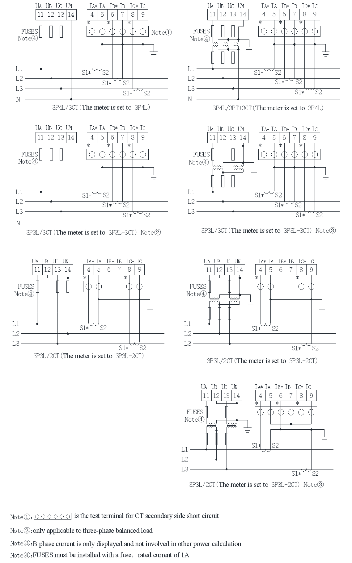
Three-phase three-wire, three-phase four-wire, see the wiring diagram;
Frequency
45~65Hz;
Voltage
Rating: AC 3*57.7/100V, AC 3*63.5/110V, AC 3*230/400V, AC 3*400/690V (96 Shape only);
Overload: 1.2 times the rating (continuous); 2x rating/1 second;
Power consumption: < 0.5VA(Every way);
Current
Ratings: AC 3x 1 (1.2) A, AC 3x5(6)A;
Overload: 1.2 times the rating (continuous); 10x rating/1 second;
Power consumption: < 0.5VA(Every way);
Measurement accuracy
Voltage, current
IEC 61557-12 0.2%
Voltage harmonics, current harmonics
IEC 61557-12 1%
Frequency
IEC 61557-12 ±0.02Hz
Active power
IEC 61557-12 0.5%
Reactive power
IEC 61557-12 1%
Active electrical energy
IEC 62053-22 0.5S class (0.2S accuracy when S is selected).
Reactive power
IEC 62053-24 Class 1
Power quality (only available when S is selected).
Waves recording
20 waveforms, 10 waves before and after;
Waveform capture
128 cycle points are stored per waveform;
Switch input
Dry contact input, built-in power supply;
Response time: less than 300ms
Relay output
Contact type: normally open contact;
Contact capacity: AC 250V/3A DC 30V/3A;
Energy pulse output
Output mode: photocoupler pulse with open collector;
Pulse constant: 10000imp/kWh (default);
communication
RS485 interface/Modbus-RTU protocol and DLT645 protocol;
RJ45 interface (Ethernet)/Modbus-TCP protocol;
Wireless interface
power supply
Working range: AC 85V~265V; DC100V~350V
Power consumption: power consumption≤15VA;
Safety
Power frequency withstand voltage
The power frequency withstand voltage between the housing and the auxiliary power supply, each input and output terminal group is AC 4kV/1min;
The power frequency withstand voltage between the auxiliary power supply and each input terminal and each output terminal group is AC 2kV/1min;
The power frequency withstand voltage between the voltage input and other input and output terminal blocks is AC 2kV/1min;
The power frequency withstand voltage between the current input and other input and output terminal blocks is AC 2kV/1min;
The power frequency withstand voltage between the relay output and other input and output terminal blocks is AC 2kV/1min;
The power frequency withstand voltage between the terminal groups of switching input, communication, analog output and pulse output is AC 1kV/1min;
Insulation resistance
Inputs、outputs to the shell>100MΩ;
Electromagnetic compatibility
Complies with IEC 61000 standard (Level 4);
Environment
Operating temperature:-25℃~+70℃;Storage temperature:-40℃~+85℃;
Relative humidity:≤95% without condensation;Altitude:≤2500m;
Protection Level
Display panel IP54; (Optionally IP65).
Standards
IEC 60068-2-1
IEC 60068-2-2
IEC 60068-2-30
Environmental Testing-Part 2-1:Tests Test A:Cold IDA
Environmental Testing Part 2-2:Tests Test B:Dry heat
Environmental Testing Part 2-30:Tests Test Db:Damp heat,cyclic (12+12h)
IEC 61000-4
Electromagnetic compatibility-Testing and measurement techniques
IEC 61557-12
Electrical safety in low voltage distribution systems up to 1 000V a.c. and 1 500V d.c –Equipment for testing, measuring or monitoring of protective measures — Part12:Performances measuring and monitoring devices(PMD)
IEC 62053-22
Electricity metering equipment (a.c.)-Particular requirements - Part22:Static meter for active energy(class 0.2S and 0.5S)
IEC 62053-24
Electricity metering equipment (a.c.)-Particular requirements - Part24:Static meter for reactive energy at fundamental frequency (classes 0.5S 1S and 1)
Dimension
Outline
faceplate size
housing size
cutout size
width
height
width
height
depth
width
height
72 square shape
75
75
66.5
66.5
82.8
67
67
96 square shape
96
96
86.5
86.5
77.8
88
88
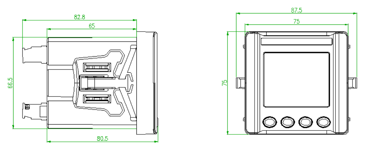
APM510 dimensional drawing
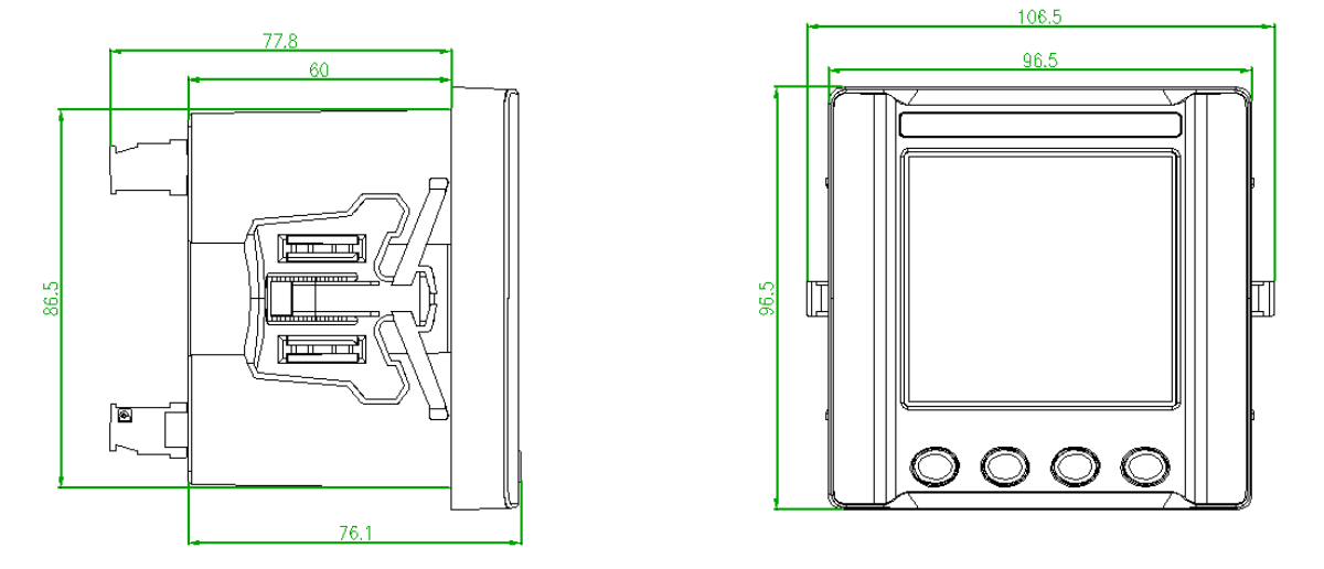
APM520 dimensional drawing
Note: If the instrument is installed side by side on the unified horizontal plane, it is recommended that the instrument opening spacing is 30mm.
Wiring
Installation


FAQ
Q: Do your company also have paired CTs for APM meters?
A: Usually, we will recommend our user to use split-core CTs called AKH-0.66/K K-φ Series or solid-core CTs called AKH-0.66/I Series to the paired with AMC meters (current input via CTs)
Q: How can I set the CT or PT ratio of APM meters?
A: Current ratio of APM meters could be set by using the keypads on APM meters and following the instruction of APM meters manual. Also, setting need to be according to the CTs or PTs ratio which were paired with APM meters. For example, if the current input is via 250A/5A CTs, the CT ratio on APM meters should be set to 250/5=50. And if the voltage input is via direct connect, PT ratio on APM meters should be set to 1. When the problem hasn’t been solved, please contact us for help.
Q: Could APM series of meters be used in IoT Energy Monitoring System for factory or building?
A: Yes, APM series of meters have standard RS485 interface and MODBUS-RTU communication protocol which allow it to be integrate with our IoT Energy Monitor Solution that can enable our users to remotely check all the data collect by energy meters like APM meters on their mobile phone or PC. For more information, please Contact us or check in IoT Energy Monitoring Solution Introduction.
Q: What is Multi-rate/tariff function? How does it work?
A: First,multi-rate/tariff function was designed to be used for billing system. Second, the electricity price of different time duration in a day is different in some country.
Energy meter with this function can measure the kwh data and assign them to several time duration in a day and put a label of spike/peak/flat/valley kwh on them respectively. And if such energy meter was connected to the billing system by using a IoT gateway, it can send the kwh data of different time duration which was with the label of spike/peak/flat/valley kwh to the billing system for calculating the electricity bill of different time duration in a day.
For example, the electricity price of spike kwh is 5 USD/1 kwh, and time duration of from 9:00 am to 11:30 am was labeled as spike kwh.
Then, if energy meter record 3 kwh used in total during 9:00 am to 11:30 am, it will send the data of 3 kwh with the label of spike kwh to the billing system, and the system calculate the electricity cost of 3x5=15USD in total from 9:00 am to 11:30 am.Other Question? Please contact us and we will get back to you as soon as possible.
Product Description:- PView
- high-performance
- requirements
-
Technical parameters
Display
Display method
Dot matrix liquid crystal; Switch between Chinese and English
Resolution
128*128;
Backlight
White LED;
Visible area
72 Shape: 38mm*46mm (1.78"/2.3");
96 Shape: 56mm*60mm (2.46"/3.2");
Signal
Electrical network
Three-phase three-wire, three-phase four-wire, see the wiring diagram;
Frequency
45~65Hz;
Voltage
Rating: AC 3*57.7/100V, AC 3*63.5/110V, AC 3*230/400V, AC 3*400/690V (96 Shape only);
Overload: 1.2 times the rating (continuous); 2x rating/1 second;
Power consumption: < 0.5VA(Every way);
Current
Ratings: AC 3x 1 (1.2) A, AC 3x5(6)A;
Overload: 1.2 times the rating (continuous); 10x rating/1 second;
Power consumption: < 0.5VA(Every way);
Measurement accuracy
Voltage, current
IEC 61557-12 0.2%
Voltage harmonics, current harmonics
IEC 61557-12 1%
Frequency
IEC 61557-12 ±0.02Hz
Active power
IEC 61557-12 0.5%
Reactive power
IEC 61557-12 1%
Active electrical energy
IEC 62053-22 0.5S class (0.2S accuracy when S is selected).
Reactive power
IEC 62053-24 Class 1
Power quality (only available when S is selected).
Waves recording
20 waveforms, 10 waves before and after;
Waveform capture
128 cycle points are stored per waveform;
Switch input
Dry contact input, built-in power supply;
Response time: less than 300ms
Relay output
Contact type: normally open contact;
Contact capacity: AC 250V/3A DC 30V/3A;
Energy pulse output
Output mode: photocoupler pulse with open collector;
Pulse constant: 10000imp/kWh (default);
communication
RS485 interface/Modbus-RTU protocol and DLT645 protocol;
RJ45 interface (Ethernet)/Modbus-TCP protocol;
Wireless interface
power supply
Working range: AC 85V~265V; DC100V~350V
Power consumption: power consumption≤15VA;
Safety
Power frequency withstand voltage
The power frequency withstand voltage between the housing and the auxiliary power supply, each input and output terminal group is AC 4kV/1min;
The power frequency withstand voltage between the auxiliary power supply and each input terminal and each output terminal group is AC 2kV/1min;
The power frequency withstand voltage between the voltage input and other input and output terminal blocks is AC 2kV/1min;
The power frequency withstand voltage between the current input and other input and output terminal blocks is AC 2kV/1min;
The power frequency withstand voltage between the relay output and other input and output terminal blocks is AC 2kV/1min;
The power frequency withstand voltage between the terminal groups of switching input, communication, analog output and pulse output is AC 1kV/1min;
Insulation resistance
Inputs、outputs to the shell>100MΩ;
Electromagnetic compatibility
Complies with IEC 61000 standard (Level 4);
Environment
Operating temperature:-25℃~+70℃;Storage temperature:-40℃~+85℃;
Relative humidity:≤95% without condensation;Altitude:≤2500m;
Protection Level
Display panel IP54; (Optionally IP65).
Standards
IEC 60068-2-1
IEC 60068-2-2
IEC 60068-2-30
Environmental Testing-Part 2-1:Tests Test A:Cold IDA
Environmental Testing Part 2-2:Tests Test B:Dry heat
Environmental Testing Part 2-30:Tests Test Db:Damp heat,cyclic (12+12h)
IEC 61000-4
Electromagnetic compatibility-Testing and measurement techniques
IEC 61557-12
Electrical safety in low voltage distribution systems up to 1 000V a.c. and 1 500V d.c –Equipment for testing, measuring or monitoring of protective measures — Part12:Performances measuring and monitoring devices(PMD)
IEC 62053-22
Electricity metering equipment (a.c.)-Particular requirements - Part22:Static meter for active energy(class 0.2S and 0.5S)
IEC 62053-24
Electricity metering equipment (a.c.)-Particular requirements - Part24:Static meter for reactive energy at fundamental frequency (classes 0.5S 1S and 1)
-
FAQ
Q: Do your company also have paired CTs for APM meters?
A: Usually, we will recommend our user to use split-core CTs called AKH-0.66/K K-φ Series or solid-core CTs called AKH-0.66/I Series to the paired with AMC meters (current input via CTs)
Q: How can I set the CT or PT ratio of APM meters?
A: Current ratio of APM meters could be set by using the keypads on APM meters and following the instruction of APM meters manual. Also, setting need to be according to the CTs or PTs ratio which were paired with APM meters. For example, if the current input is via 250A/5A CTs, the CT ratio on APM meters should be set to 250/5=50. And if the voltage input is via direct connect, PT ratio on APM meters should be set to 1. When the problem hasn’t been solved, please contact us for help.
Q: Could APM series of meters be used in IoT Energy Monitoring System for factory or building?
A: Yes, APM series of meters have standard RS485 interface and MODBUS-RTU communication protocol which allow it to be integrate with our IoT Energy Monitor Solution that can enable our users to remotely check all the data collect by energy meters like APM meters on their mobile phone or PC. For more information, please Contact us or check in IoT Energy Monitoring Solution Introduction.
Q: What is Multi-rate/tariff function? How does it work?
A: First,multi-rate/tariff function was designed to be used for billing system. Second, the electricity price of different time duration in a day is different in some country.
Energy meter with this function can measure the kwh data and assign them to several time duration in a day and put a label of spike/peak/flat/valley kwh on them respectively. And if such energy meter was connected to the billing system by using a IoT gateway, it can send the kwh data of different time duration which was with the label of spike/peak/flat/valley kwh to the billing system for calculating the electricity bill of different time duration in a day.
For example, the electricity price of spike kwh is 5 USD/1 kwh, and time duration of from 9:00 am to 11:30 am was labeled as spike kwh.
Then, if energy meter record 3 kwh used in total during 9:00 am to 11:30 am, it will send the data of 3 kwh with the label of spike kwh to the billing system, and the system calculate the electricity cost of 3x5=15USD in total from 9:00 am to 11:30 am.Other Question? Please contact us and we will get back to you as soon as possible.
Related Products

Product inquiry
We will contact you within one working day. Please pay attention to your email.
Newsletter
Sign up our newsletter to get update news and article about company.