
![[object Object]](https://omo-oss-image.thefastimg.com/portal-saas/new2023080419495759710/cms/image/138ba837-b50d-4ff3-a73c-2e6a2379c522.jpg "[object Object]")


ARD3T CE Approved Smart Motor Protectors for Protecting Motors and Power Monitoring
Series of products: Products
Series of products: Power Monitoring and Controlling Devices
Series of products: Smart Motor Protectors


- Product Description
- Parameters
- Q&A
- Download
-
Overview
ARD3T Intelligent Motor Protector (hereinafter referred to as ARD3T) is sub-family product of ARD series low voltage motor protectors by Shanghai Acrel Co., LTd.
Among the same domestic industry, ARD3T is the first modular design product and supplies a gap in low voltage motor protector field in China. ARD3T belongs to the projects of Ministry of Science and Technology, this project is granted honors including 12 patents, 2 computer copyrights and product standard for record, and etc.
ARD3T takes the lead in technology in China. ARD3T consists of master module, measurement module, switching value module,analog value module, temperature module, communication module, and LCD module.
This product has little volume, compact structure, and is suitable to the motors with the rated voltage up to AC 660V, the rated current up to AC 800A, and 50/60Hz rated frequency.The product can be directly installed for using in low voltage control terminal cabinets or all kinds of drawer cabinets of 1/4 modulus and above, and has improved reliability and automation of the control circuit loop.
Product executive standard: GB/T14048.1 Low-voltage switchgear and controlgear-Part 1:General rules GB14048.4 Low-voltage switchgear and controlgear- Electromechanical contactors and motor-starters JB/T10736—2007 Low-voltage motor protectors GB/T20540.1-6—2006 Digital data communication for measurement and control - Fieldbus for use in industrial systems Type 3: PROFIBUS specification
Dispaly
Application

Function
● Auxiliary power supply supports AC/DC 110/220V or AC 380V (380V power supply module is needed separately)
● Modular design, it consists of master module, measurement module, switching value module, analog value module, temperature module, communication module, and LCD module.
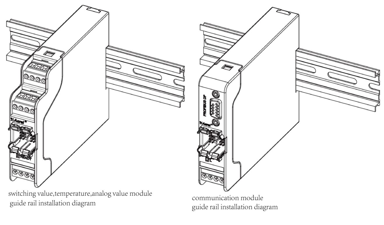
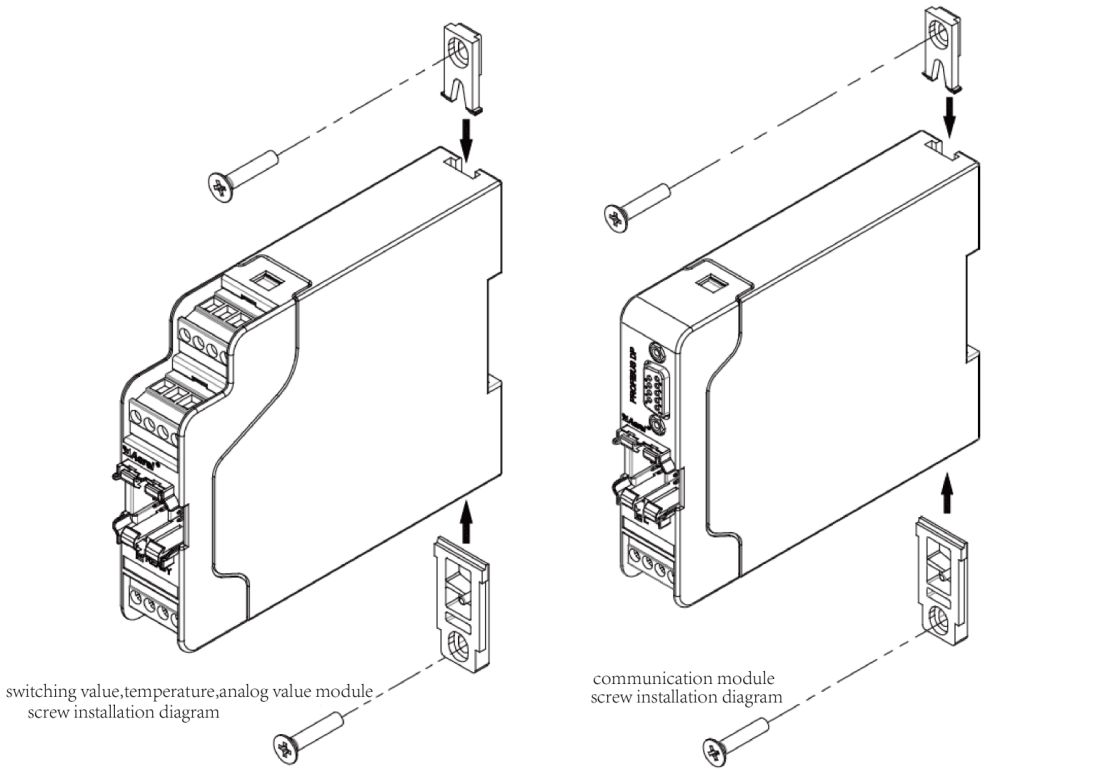
● Small volume, support guide rail and screw fixed installation
● Additional module adopt bus power supply, do not need external auxiliary power supply
● With upper computer configuration software, the product is convenient for customer to set parameter and program;
● DI/DO programmable freely;
● DI support dry contact(Electronic)or wet contact(Electric) input,and wet contact can choose AC or DC power supply;
● Standard configuration about overall comprehensive motor protection functions such as overload protection, stalling protection, blocking protection, under-load protection, phase failure protection, phase unbalance protection, PTC protection, external failure protection, and etc
● Standard configuration about various starting mode such as protection module mode, direct starting, Y-△ starting, auto-transformer step-down starting, two-directional starting, single winding two-speed starting, duplex winding two-speed starting, and etc.The starting mode can be set at spot.
● Standard configuration about fault record and operation management information, facilitate to find the cause of fault and maintain the motor.
● Standard configuration about self-starting function, it can implement anti-interference electricity and voltage off restarting function by using additional anti-interference electricity module.
● LCD display
● Implement 2-channel 4-20mA input test and 2-channel 4-20mA transmitting output by using anlalog value module.Users can freely set the corresponding parameters of 4-20mA transmitting output.
● Implement 3 channels temperature measure protection by using temperature module, the optional type of external sensor is PT100,PT1000,Cu50,PTC, and NTC.
● Implement Profibus-Dp communication by using Profibus module.
Network
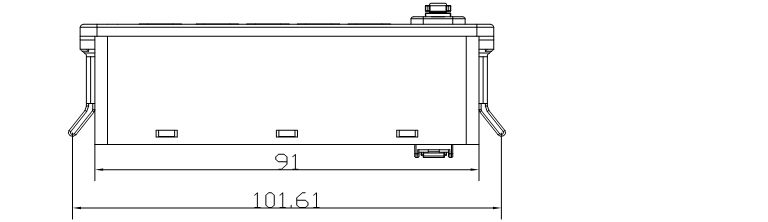
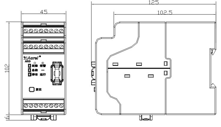
Dimension

Wiring

Installation
 Product Description:
- PView
- high-performance
- requirements
-
Function configuration
Function configuration of ARD3T is as shown in Table 1
Table1 Function configuration
Type
Function
Function configuration
Standard functions
Selected functions
Protection function
Overload
√
Phase failure/unbalance
√
Rotor clocked
√
Blocking
√
Short circuit breaking
√
Starting overtime
√
Underload
√
Feedback overtime
√
Master temperature protection
√
Master temperature sensor fault
√
External fault
√
Modular structure fault
√
Inner fault
√
Residual current
Grounding
√
Leakage
√(Leakage)
Phase sequence
√(Voltage function)
Under voltage
Over voltage
Under power
tE time
√(Special safe protection)
Voltage off restarting function(anti-interference electricity)
√(Voltage off restarting function(anti-interference electricity))
4~20mA input protection
√(analog module is fitted with 2 input function)
Module temperature protection
√(Temperature module)
Module temperature sensor fault
Control function
Protection mode
√
Direct starting
Two-directional starting
Single winding two-speed starting
Duplex winding two-speed starting
Y-△ starting(two relays)
Auto transformer starting (two relays)
Self-starting
Communication function
Modbus
√(Master communication function)
Double Modbus
√(Communication module)
Profibus
√(Communication module)
Switching input and output
Master 4DI,4DO
√
Switching value module 4DI,3DO
√ (Switching value module)
Analog value output
DC 4~20mA
√Analog value module is fitted with output function
Fault record
8 records, record the reason, time and various parameters of the motor when fault occur
√
Operation information
Record operation information such as starting, stopping, numbers of tripping, operating time, stopping time,and etc
√
Logic function
Timer
√
Counter
√
Truth table
√
Testing parameter
3-phase current
√
Leakage current measurement
√(Leakage function)
3-phase line voltage, power, power factor, electric energy
√(Voltage function)
PTC/NTC
√Master temperature
4-20mA input
√Analog value module fitted with two input function
Temperature module
√(temperature module)
Parameter setting and query(LCD display)
Parameter query
Parameter measurement
√Display module
Alarm query
Fault query
Switching value status
Operation information
Parameters setting
Protection setting
Starting parameters setting
System parameters setting
-
1. ARD3T of 100A and below single field direct starting
Notes:
1.Switching input adopts dry contact, ARD3T provides DC+24V power supply itself.
2.Without voltage, leakage, temperature protection function, the corresponding terminals should not be wired.
3.This figure defines D01 as starting1, D02 as any fault tripping close, and D04 as fault output of circuit breaker which need disjunction, for example: short circuit or grounding.
4.This figure defines DI1 as starting1, DI2 as starting 2, and DI3 as stopping.
5.The standard configuration connecting line between master and measurement module is 1m, and the connecting line between master and display module is also 1m.
6.The wiring of current transformer in this figure is used for ARD3T of 100A and below.
2. ARD3T of 100A and below single bidirectional field starting
Notes:
1.Switching input adopts dry contact, ARD3T provides DC+24V power supply itself.
2.Without voltage, leakage, temperature protection function, the corresponding terminals should not be wired.
3.This figure defines D01 as starting1, D02 as any fault tripping close, and D04 as fault output of circuit breaker which need disjunction, for example :short circuit or grounding.
4.This figure defines DI1 as starting1, DI2 as starting 2, and DI3 as stopping.
5.The standard configuration connecting line between master and measurement module is 1m, and the connecting line between master and display module is also 1m.
6.The wiring of current transformer in this figure is used for ARD3T of 100A and below.
3. ARD3T of 100A and below single Y-△ field starting
Notes:
1.Switching input adopts dry contact, ARD3T provides DC+24V power supply itself.
2.Without voltage, leakage, temperature protection function, the corresponding terminals should not be wired.
3.This figure defines D01 as starting1, D02 as any fault tripping closing, and D04 as fault output of circuit breaker which need disjunction, for example: short circuit or grounding.
4.This figure defines DI1 as starting1, and DI3 as stopping.
5.The standard configuration connecting line between master and measurement module is 1m, and the connecting line between master and display module is also 1m.
6.The wiring of current transformer in this figure is used for ARD3T of 100A and below.
4. ARD3T of 100A and below single auto-transformer step-down field starting
Notes:
1.Switching input adopts dry contact, ARD3T provides DC+24V power supply itself.
2.Without voltage, leakage, temperature protection function, the corresponding terminals should not be wired.
3.This figure define D01 as starting1, D02 as any fault tripping closing, and D04 as fault output of circuit breaker which need disjunction,for example:short circuit or grounding.
4.This figure defines DI1 as starting1, and DI3 as stopping.
5.The standard configuration connecting line between master and measurement module is 1m, and the connecting line between master and display module is also 1m.
6.The wiring of current transformer in this figure is used for ARD3T of 100A and below.
5. ARD3T of 100A and below single two-speed single winding field starting
Note:
1.Switching input adopts dry contact, ARD3T provides DC+24V power supply itself.
2.Without voltage, leakage, temperature protection function, the corresponding terminals should not be wired.
3.This figure defines D01 as starting1, D02 as any fault tripping closing, and D04 as fault output of circuit breaker which need disjunction, for example: short circuit or grounding.
4.This figure define DI1 as starting1, DI1 as starting2,and DI3 as stopping.
5.The standard configuration connecting line between master and measurement module is 1m, and the connecting line between master and display module is also 1m.
6.The wiring of current transformer in this figure is used for ARD3T of 100A and below.
6. ARD3T of 100A and below single two-speed duplex winding field starting
Notes:
1.Switching input adopts dry contact, ARD3T provides DC+24V power supply itself.
2.Without voltage, leakage, temperature protection function, the corresponding terminals should not be wired.
3.This figure defines D01 as starting1, D02 as any fault tripping closing, and D04 as fault output of circuit breaker which need disjunction,for example:short circuit or grounding.
4.This figure define DI1 as starting1, DI1 as starting2,and DI3 as stopping.
5.The standard configuration connecting line between master and measurement module is 1m, and the connecting line between master and display module is also 1m.
6.The wiring of current transformer in this figure is used for ARD3T of 100A and below.
7. ARD3T single frequency conversion starting
Notes:
1.Switching input adopts dry contact, ARD3T provides DC+24V power supply itself.
2.Without voltage, leakage, temperature protection function, the corresponding terminals should not be wired.
3.This figure defines D01 as starting1, D02 as any fault tripping closing, and D04 as fault output of circuit breaker which need disjunction,for example:short circuit or grounding.
4.This figure defines DI1 as starting1, and DI3 as stopping.
5.The standard configuration connecting line between master and measurement module is 1m, and the connecting line between master and display module is also 1m.
6.The wiring of current transformer in this figure is used for ARD3T of 100A and below.
8. ARD3T soft starting wiring diagram(1)
Notes:
1.This figure defines starting mode as protection mode, D01 as starting1, D02 as any fault tripping closing
2.The standard configuration connecting line between master and measurement module is 1m, and the connecting line between master and display module is also 1m.
3.Current transformer's wiring refers to other ARD3T illustration.
9. ARD3T soft starting wiring diagram(2)
Notes:
1.This figure define stating mode as direct mode, D01 as starting1, D02 as any fault tripping closing
2.This figure defines DI1 as starting, DI3 as stopping, and DI4 as resetting.
3.The standard configuration connecting line between master and measurement module is 1m, and the connecting line between master and display module is also 1m.
4.Current transformer's wiring refers to other ARD3T illustration.
Related Products

Product inquiry
We will contact you within one working day. Please pay attention to your email.
Newsletter
Sign up our newsletter to get update news and article about company.